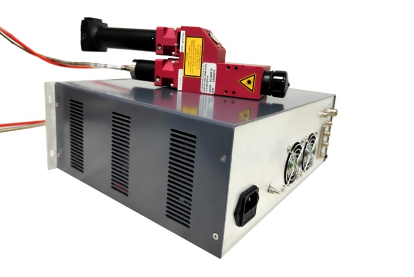
The LBS mini (Dual Spot) dual spot system is suitable for laser miniature repair, electronic component repair welding and other scenarios. This laser system has two adjustable spot sizes, spacing, and energy ratios, and is equipped with an ultra high speed closed-loop control pyrometer. Combined with unique optical shaping technology, the spot size can be controlled within a precise range, and the energy distribution is highly uniform, achieving precise temperature control within a very small range. Compared to single spot laser systems on the market, the LBS mini (Dual Spot) dual spot system can perfectly avoid the impact on the gap between the two solder pads on the substrate and solve the problem of “standing a monument” during the welding process. In addition, the control software used in the entire system – LASCON ® Software, with real-time temperature measurement and adjustment of laser energy function, universal TCP/IP protocol for easy integration by customers; The software script writing process is simple and easy to get started, making the use and operation of the laser system more convenient and efficient; Can save 500000 processes and 255 process control scripts.
More compact design without the need for complex structures;
Higher cost-effectiveness, a single laser light source can have two spots;
It can be compatible with the repair of various electronic components of different sizes on the same PCB board.
2.Why choose LBS mini (Dual Spot) dual spot system
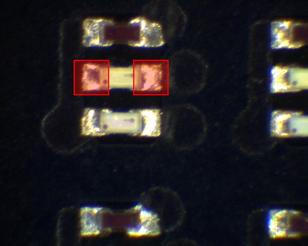
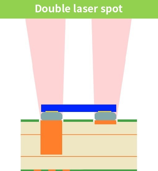
①Using dual light spots to illuminate both ends of the miniature chip can perfectly avoid the impact on the gap between the two solder pads on the substrate.
②The use of dual light spots and different laser energies on the two end pads can perfectly solve the problem of “monument”.
3.Our technological advantages
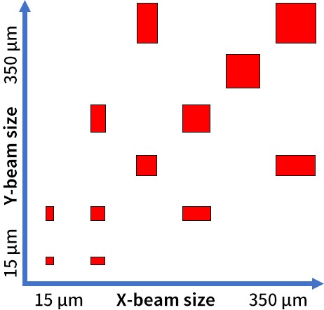
①Adaptive spot
The LBS mini (Dual Spot) dual spot system can achieve free adjustment of spot size, spacing, and energy ratio.
Spot size can be adjusted
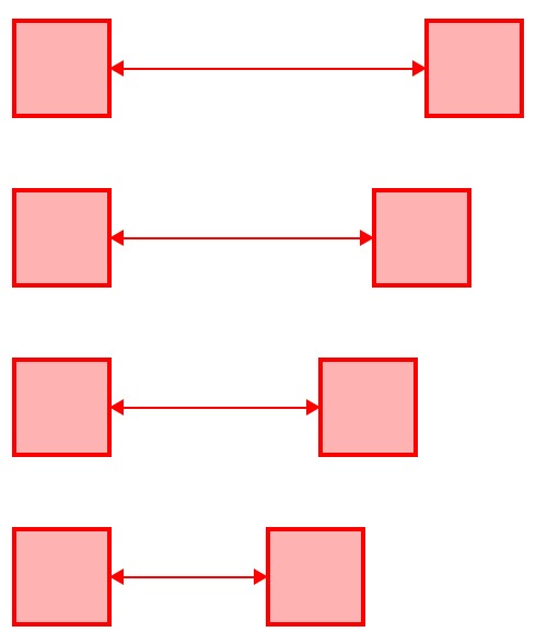
Spot spacing can be adjusted
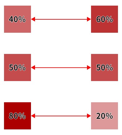
The ratio of dual spot energy can be adjusted
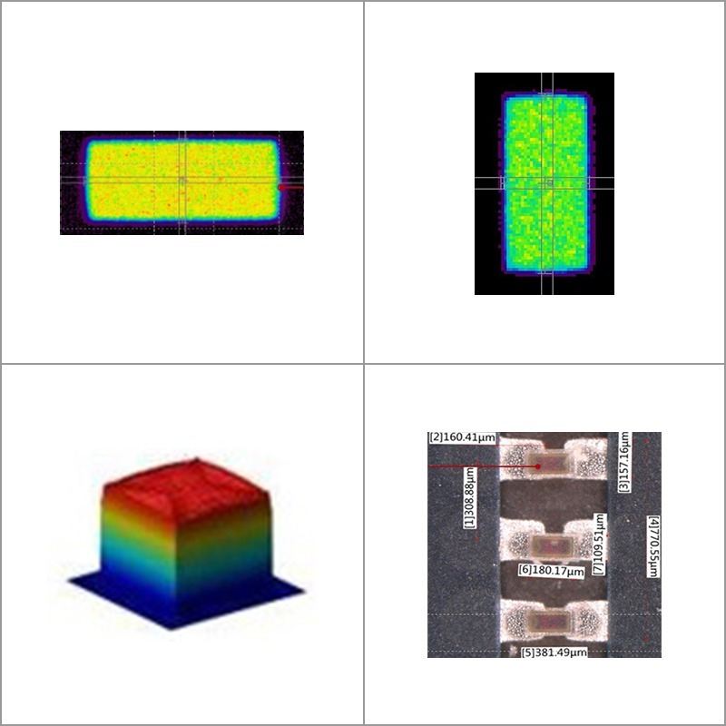
②Uniform and shaped laser spot
Our top hat beam profile has high beam uniformity. Sharp contours prevent damage to surrounding areas.
Plastic shaped light spots and compatible products.
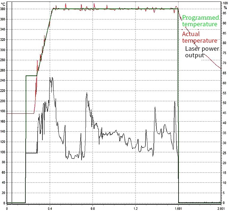
③Temperature control
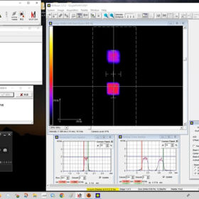
Lascon® controller is connected to the laser. It allows for fast, precise, and accurate material surface temperature control.
The figure shows that the laser system changes the laser temperature through high-speed closed-loop control of the pyrometer feedback, achieving the pred- etermined temperature curve.
Laser system specifications
Serial Number
Parameter
Unit
Details
1
Laser power
W
30, 60, 100
2
Wavelength
nm
975
3
Power adjustment range
%
0~100
4
Pilot light
–
Yes
5
Fiber core diameter
µm
200 or customized
6
Numerical aperture
–
0.22
7
Fiber length
m
3, 5 or customized
8
Connector
–
SMA905 or D80
9
Input voltage
V
200~240(50-60Hz)
10
Operating mode
–
Continous wave (CW)
11
Maximum modulation frequency
Hz
20000
12
Control mode
–
External control touch screen, RS232 serial port, analog AD
13
Cooling method
–
air cooling
14
Working temperature
℃
15-30
15
Storage temperature
℃
5-50
16
Cooling requirement
–
10 cm open space around it
17
Laser safety class
–
DIN EN 60825-1, class 4
Laser head specifications
Serial Number
Parameter
Unit
Special laser head
1
Power limit
W
up to 500
2
Spectral range
nm
975
3
Optics
–
1″, AR coated, 23mm max aperture
4
Fibre connector
–
FSMA905, D80, LLK-A (connection of various fibre laser collimators available)
5
Fibre diameter
µm
100 – 600
6
Numerical aperture
–
0.22
7
Pilot laser
–
Class 2. Wavelength 650nm +/- 10nm, via fibre coupled pyrometer
8
Ambient temperature
℃
5-55 for operation, no condensation
9
Dimensions
mm
165 * 99.5 * 330.3
10
Weight
kg
1.2658
11
Protection
–
IP50
12
CE label
–
According to EU directives for electromagnetic immunity
13
Conformity
–
The RoHS Directive 2011/65/EU of 2011-06-08 with supplement from 2015-03-31 is fulfilled
14
Camera
–
USB2.0 1280 x 1024, coaxial with pyrometer and laser
15
0.8kg without the camera
Controller specifications
Serial Number
Parameter
Unit
Details
1
Temperature range
℃
100 – 2200
2
Spectral range
µm
1.65 – 2 / 1.65 – 2.5
3
Accuracy (e=1, t90=1s, T=25℃)
–
< 1500℃ 0.3% +/- 2K
4
Repeatability
–
0.1% +/- 1K
5
Resolution
℃
0.1
6
Response time
ms
0.1
7
Emissivity
–
0.01 – 1
8
Analog output
V
0-10 (16Bit configurable using software)
9
Power supply
–
24V DC, max. 2A
10
Data storage
–
internal, 500.000 processes, 255 process control scripts
11
Optical fibre length
m
3, 5 or customized
12
Ambient temperature
℃
max 40
13
CE label
–
According to EU directives for electromagnetic immunity
14
Conformity
–
The RoHS Directive 2011/65/EU of 2011-06-08 with supplement from 2015-03-31 is fulfilled
15
Software
–
Includes LASCON® software
16
Position
–
Coaxial
LASCON® is the process monitoring system with probably the largest distribution in the laser industry. More than 1500 users worldwide in industry and research monitor and regulate their laser processes with LASCON®.
The LASCON Process Manager uses the infrared or 2 color pyrometers to measure the temperature on the workpiece 10,000 times per second and compares the measured temperature with a specified setpoint temperature. From the difference, the systems calculated the rated power for the laser system. This laser system is controlled by an analogue signal so that any laser system can be used with analog voltage power input. But it can also control inductors and other heat sources. The processes are monitored, stored and visualized. The process data of each process can additionally be exported automatically to an external server. Easily programmable scripts can be used to set monitors around setpoint temperatures to create an error signal if the measured temperature is not within the temperature monitor. Especially for laser soldering, the solder wire feeder can also be parameterized and started by software from the script.
MiniLED repair
MiniLED repair is a necessary step in the product manufacturing process, which mainly involves repairing MiniLED components that are damaged during the reflow process due to solder defects, misalignment, burning, and other reasons. There are two heating processes during the MiniLED repair process: first, the faulty component must be removed from the PCB through heating. Secondly, clean the solder pads to ensure correct formation of solder joints, and then place the new miniLED in the desired position and solder it onto the PCB. In order to meet the needs of the MiniLED repair process in the appeal, we provide a standard tool – LBS mini laser system.
 DYNALAS
1-1.jpg)
1-1-280x280.jpg)
2-1-280x280.jpg)
3-1-280x280.jpg)
 LASCON® is the process monitoring system with probably the largest distribution in the laser industry. More than 1500 users worldwide in industry and research monitor and regulate their laser processes with LASCON®.
 MiniLED repair